Well, maybe its not a proper bridge in model railroad terms. I suppose most people might call it a ‘duck under’, though I wouldn’t try it. At any rate, it is a moveable span that crosses the main travel path into and out of the basement. And while it isn’t much to look at, I am quite proud of it.
First, the railroad requirements. Crossing the aisle means access to a large, almost totally unutilized section of the basement. A place where I can spread out a little, and build tracks for permanent staging as well as locomotive storage (wait or it!). The assembly tracks, which are already in place, tail off and connect to the staging tracks, engine storage area and a balloon track for turning trains, all at about the same place. Here’s the track plan I worked out –

Now, the real world requirements. It had to be quick and easy to move; the main traffic path cannot be obstructed. When I say main traffic path, I mean it. Not only is it the main path for ALL foot traffic in and out (via the stairs), but also for moving heavy and bulky items via ‘the scuttle’ – a small door that allows direct access to the outside.
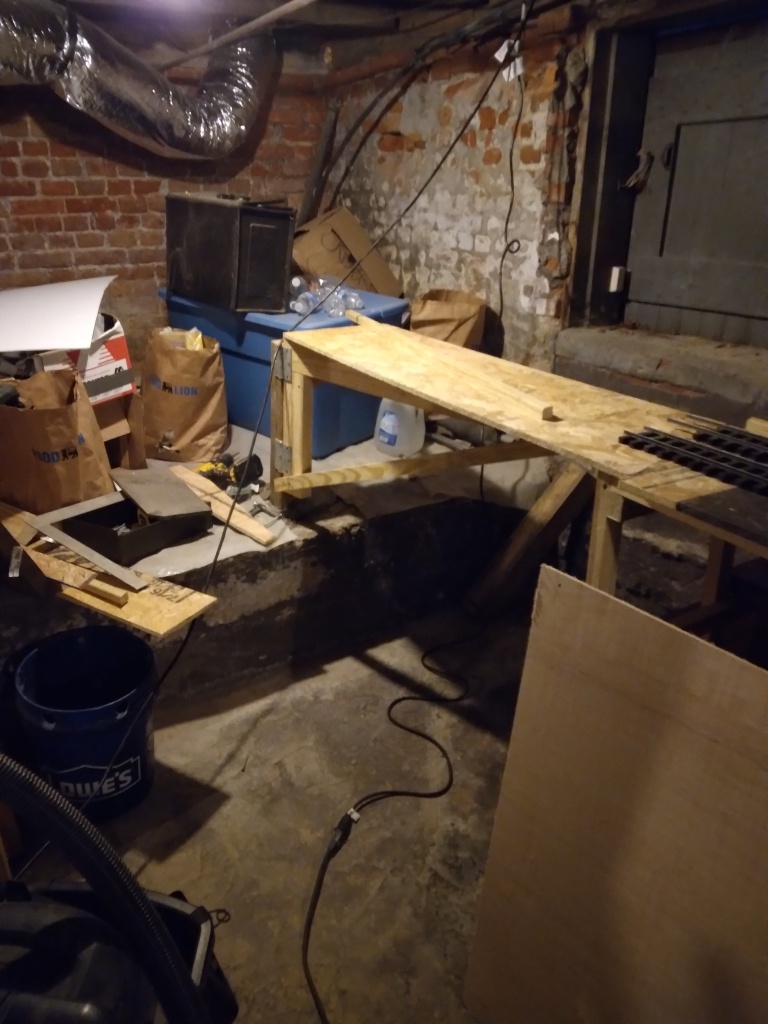
The environment in the basement is not as friendly as it may seem, either. I always cringe a bit looking at photos, and can’t imagine ever giving tours down there – the basement is rather a mess. More than 200 years of repairs and patches and piecemeal work have made quite an ugly patchwork of the place. It is usually reasonably dry, at least. But everything I build down there is being built as if it were outside.
On to design. After debating whether or not to build an actual model of a bridge that swings, I settled on a less attractive but easier approach – I just built a platform as if it were an extension of the benchwork under the assembly tracks, except that it’s hinged like a garden gate. A robust structure makes it easy to just pull or shove it out of the way to get through as needed. It hinges to a post that is set in the dirt floor like a fencepost but purposefully out of plumb, leaning such that the ‘gate’ I created swings out but also lifts, so that when released it swings closed by gravity alone. The rails atop it line up when the gate is closed at rest, and presently there is no lock. More on that later.
The deck is 3/8″ particle board supported in various locations by strips of 5/4 pressure treated decking and a pressure treated 2×4 backbone. The whole mess is attached with drywall screws and some old galvanized hinges I found in my box of spares and cleaned up, and painted with the same chocolate brown opaque outdoor wood stain.


As I say, it isn’t much to look at but I am quite proud of it.
Now, a word about future thoughts.
The engine storage area is going to be a roundhouse. The turntable will face away from viewers, so the stalls will be against the aisle, allowing access to the locos inside for charging, etc. I have a notion of making the stall tracks removable on trays, so locos can be lifted out and moved over to a workbench for real maintenance and repair as needed. Right now I’m scoping out prototypes to model. I don’t like the look of the ancient Seaboard roundhouse that was here in town, so I’ve been looking for other inspiration.

I rather like this one better –

Now, the other thing brewing…
Since most of the switches are situated so close together, I want to do something cool to control them. Every computer simulation of the layout I’ve built has an interlocking tower on the curve just over where the bridge is now. No idea why really, I always just put one there. What I would really like to do is build a miniature interlocking plant on the inside of the turn – complete with working point rodding. I’ve always had a fascination with those, and, I mean, if you can’t do it in G gauge when can you do it, right?
I’ve also found some really cool old articles from Model Railroader, published in 1961, about making the mechanical interlocking plant – check them out here.
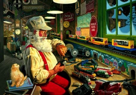
Anyway, just like when I was a kid, my head is swimming with model trains this Christmas. I hope all my fellow model railroaders are similarly enjoying the season. After all…
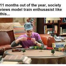
But this month, we’re thought of like this…